Hardware Sound
Now the fun begins, making the Feather M4 beep.
The sound producer is a Large Enclosed Piezo Element w/Wires.
Piezo elements convert vibration to voltage or voltage to vibration. That means you can use this as a buzzer for making beeps, tones and alerts AND you can use it as a sensor, to detect fast movements like knocks.
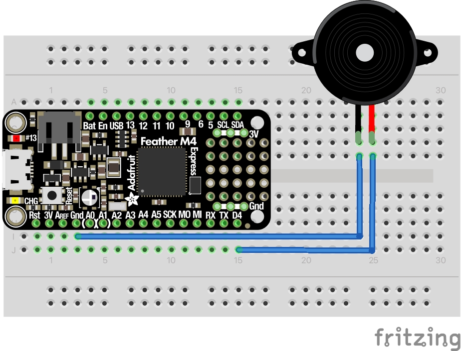
Below is a breadboard diagram showing how I hooked it up initially.

In order to make tones from this setup, we need to raise and lower the voltage presented to the piezo at a particular frequency. While we could do that with a digital output pin and some careful timing, here we don’t need to. The ATSAMD family has Pulse-width modulation(PWM) features on some of the digital pins, where you can set a duty cycle and frequency. With that, all we need to do is enable and disable the PWM when we want tone or silence and change the frequency as needed. I chose pin D4 as I won’t need to use it for the display and it supports PWM.
Here’s the code to make it beep. Much of it is similar to making the LED blink. I’m pulling in the same NOTES array that I used in the simulator.
#![no_std]
#![no_main]

use feather_m4 as bsp;

use bsp::{
    ehal::blocking::delay::DelayMs,
    entry,
    hal::{
        clock::GenericClockController,
        delay::Delay,
        gpio::F,
        prelude::*,
        pwm::{Channel, TCC2Pinout, Tcc2Pwm},
    },
    pac::{CorePeripherals, Peripherals},
};
use panic_semihosting as _;
use quinti_maze::game::NOTES;

#[entry]
fn main() -> ! {
    let mut peripherals = Peripherals::take().unwrap();
    let core = CorePeripherals::take().unwrap();
    let mut clocks = GenericClockController::with_external_32kosc(
        peripherals.GCLK,
        &mut peripherals.MCLK,
        &mut peripherals.OSC32KCTRL,
        &mut peripherals.OSCCTRL,
        &mut peripherals.NVMCTRL,
    );
    let pins = bsp::Pins::new(peripherals.PORT);

    let buzzer = pins.d4.into_alternate::<F>();
    let gclk0 = clocks.gclk0();

    let mut pwm = Tcc2Pwm::new(
        &clocks.tcc2_tcc3(&gclk0).unwrap(),
        440.hz(),
        peripherals.TCC2,
        TCC2Pinout::Pa14(buzzer),
        &mut peripherals.MCLK,
    );

    let max_duty = pwm.get_max_duty();
    pwm.set_duty(Channel::_0, max_duty / 2);
    pwm.disable(Channel::_0);

    let mut delayer = Delay::new(core.SYST, &mut clocks);
    for (freq, duration, delay) in NOTES {
        delayer.delay_ms(*delay as u32);
        pwm.set_period(freq.hz());
        pwm.enable(Channel::_0);
        delayer.delay_ms(*duration as u32);
        pwm.disable(Channel::_0);
    }
    pwm.disable(Channel::_0);

    loop {}
}
When run, it sounds good.
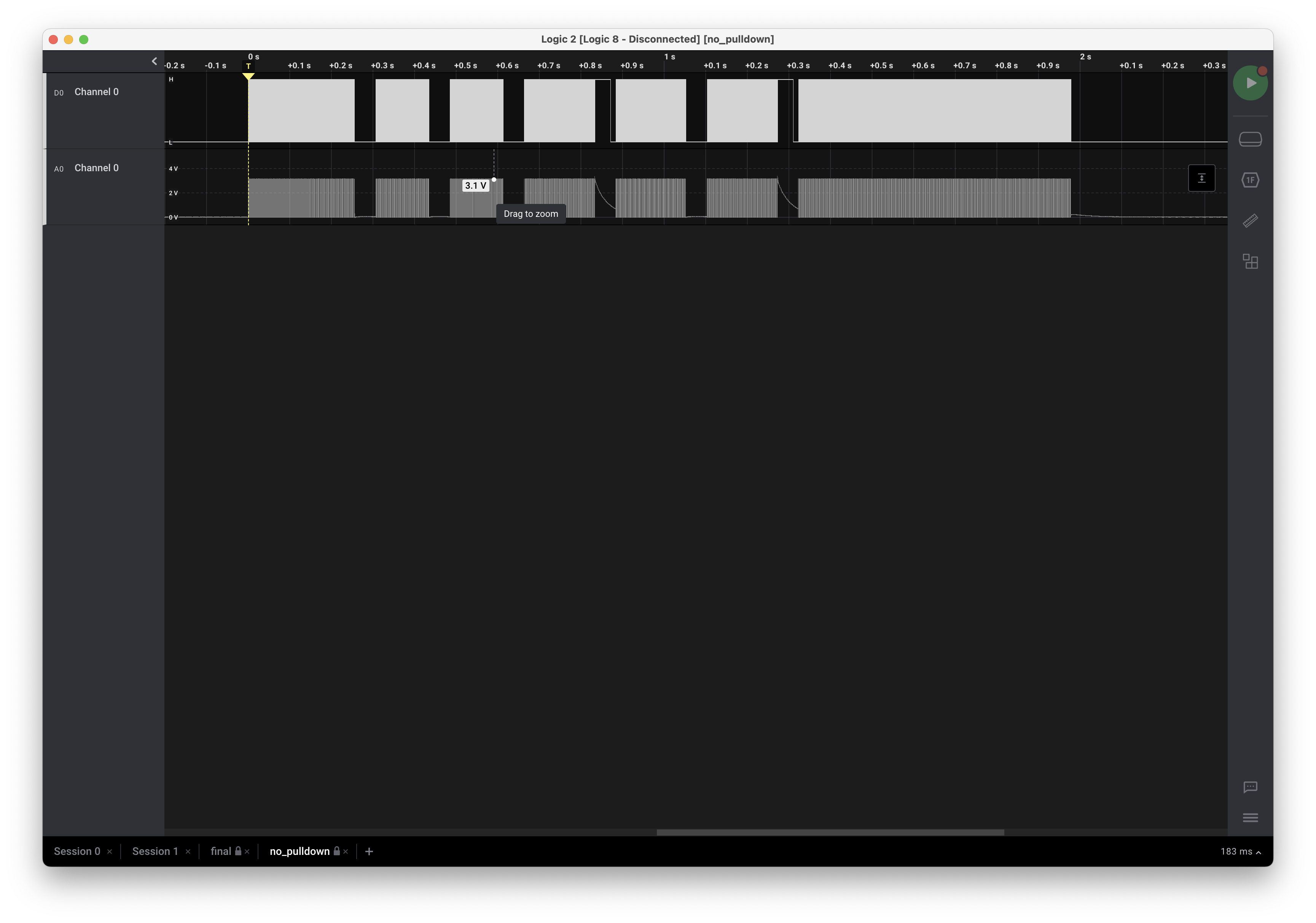
Just for fun I hooked up the output of D4 to my beloved Saleae Logic 8 and I was quite surprised at the waveform. In the image below, the top is the channel represented digitally and the bottom is the actual voltage measurement.
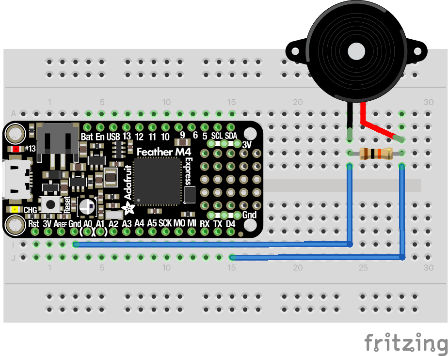
At the end of the fourth and sixth notes it takes quite a while for the voltage on the output pin to drop. I can’t really explain it, but perhaps there’s something about the resistance or capacitance of a piezo that I don’t understand. Since voltage failing to drop suggests a lack of a path to ground I tried adding a 10㏀ resistor in parallel with the piezo.

Which produced the following trace.
I feel much better, even though I can’t tell the difference in the sound. I do wonder why it’s needed, though, perhaps a reader with a better understanding of the electronics can explain it to me.
The last thing I noticed was that Saleae was telling me the duty cycle wasn’t always 50%. It changed depending on the frequency of the note.
Pulse width modulation devices in embedded Rust are defined by the Pwm
trait. The Duty
type says…
The implementer is free to choose a float / percentage representation (e.g. 0.0 .. 1.0) or an integer representation (e.g. 0 .. 65535)
…which is an interesting choice, as semantically those two are very different. ATSAMD chose an integer representation.
By inspection I found that the max duty value changes with frequency, which makes sense, so I have to set it every time I change the frequency of the tone. After that, Saleae reports almost exactly 50% duty cycle on each square wave.
With that, I feel I’ve reached parity with some 1982 Applesoft BASIC code.

